


The principle of communication antennas and accessories,
how to better receive and transmit signals for 3g/4g signal repeater amplifiers?
Website: https://www.lintratek.com/
First, the antenna principle:
1.1 Definition of antenna:
A device that can effectively radiate electromagnetic waves to a specific direction in space or can effectively receive electromagnetic waves from a specific direction in space.
1.2 Antenna functions:
Ø Energy conversion – conversion of guided wave and free space wave; Directional radiation (reception)- has a certain directivity.
1.3 Antenna radiation principle:

1.4 Antenna Parameters
Radiation parameter
Ø Half power beam width, front to back ratio;
Ø polarization mode, cross polarization discrimination;
Ø Directivity factor, antenna gain;
Ø Main lobe, secondary lobe, sidelobe suppression, zero filling, beam downtilt…
Circuit parameter
Voltage standing wave ratio VSWR, reflection coefficient Γ, return loss RL;
Ø Input impedance Zin, transmission loss TL;
Ø isolation Iso;
Ø Passive third order Intermodulation PIM3…
Antenna sidelobe

Horizontal Beam Width

Front to back ratio: Specifies the ratio of the forward radiated power to the antenna and the backward radiated power within ±30°.

The relationship between gain and antenna size and beamwidth
Flattening the “tire”, the more concentrated the signal, the higher the gain, the larger the antenna size, and the narrower the beamwidth;

A few key points of antenna gain:
The antenna is a passive device and cannot produce energy. Antenna gain is simply the ability to effectively concentrate energy to radiate or receive electromagnetic waves in a specific direction.
Ø The gain of the antenna is generated by the superposition of the vibrators. The higher the gain, the longer the antenna length. Increase the gain by 3dB and double the volume.
The higher the antenna gain, the better the directivity, the more concentrated the energy, and the narrower the lobe.
1.5 Radiation Parameters
Polarization: refers to the trajectory or change of the electric field vector in space.
1.6 Circuit Parameters
Return loss

Two, antenna products
2.1 Antenna Naming Method:

Antenna categories :ODP(outdoor directional plate antenna),OOA(outdoor omnidirectional antenna),IXD(indoor ceiling antenna),OCS(outdoor bidirectional antenna), OCA(outdoor cluster antenna), OYI(outdoor Yagi antenna), ORA(outdoor throwing surface antenna), IWH(indoor wall mounted antenna) and so on.
Half power Angle :032,065,090,105,360(base station antenna) 020,030,040,050,060,075,090,120,160,360 (repeater antenna)
Polarization mode: R(dual polarization), V(single polarization)
Gain: The maximum value is 21dbi based on the actual value
Joint types: D(Din head), N(N-type head), S(SMA head), T(TNC head) and so on
Frequency band:
Specification code: The Roman letters indicate the generation of the product. The following letters and numbers indicate the dip Angle, shape, and other information. F type; V electric regulation; RV remote electric modulation
2.2 Base Station Antenna
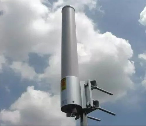
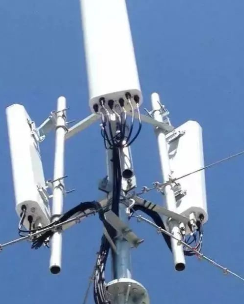
Omnidirectional Antenna Dual-Frequency Antenna
Three-Frequency Antenna
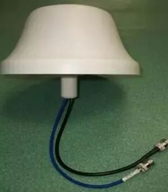
Ceiling Antenna
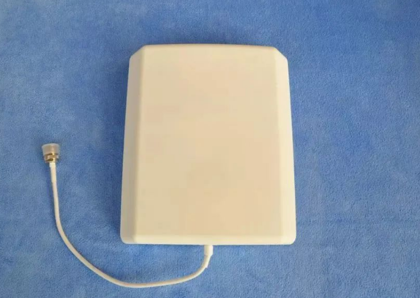
Wall Mounted Antenna
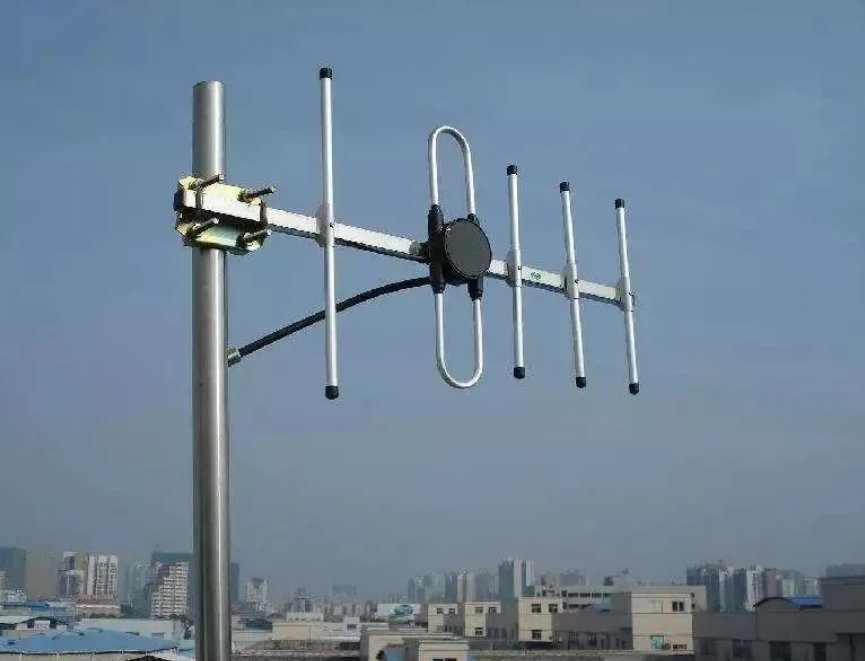
Yagi Antenna
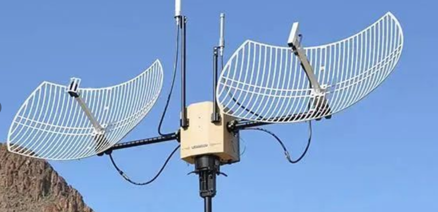
Grid Antenna
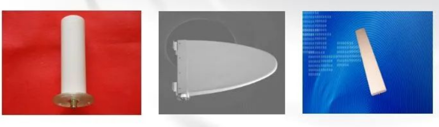
Broadband Omnidirectional Antenna Log-Periodic Antenna Plate Antenna
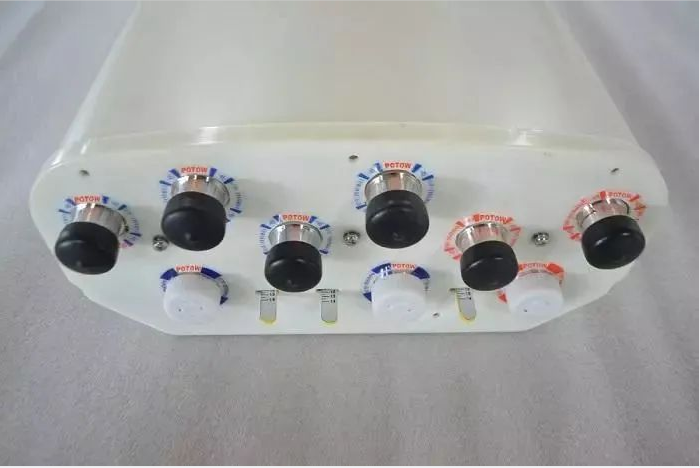
3.1 Power Divider
The power divider is a device that divides the energy of one output signal into two or more outputs. It’s essentially an impedance converter.
Ø Can the power divider be reversed to replace the combiner?
When used as a synthesizer, it not only requires high isolation, low standing wave ratio, but also focuses on the requirement to withstand high power. Considering that the output ports of the commonly used cavity power splitter do not match, large standing wave; Because of the low power resistance of the microstrip power splitter, we do not recommend using the power splitter to replace the combiner.
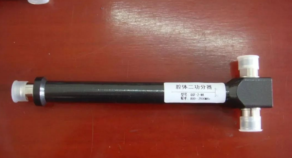
Cavity Power Divider
Four, the coupler introduction
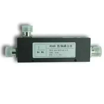
4.1 Coupler
Ø Coupler is a kind of component that distributes the energy of the input signal through the electric field and magnetic field coupling to become a part of the coupling end output, and the rest of the output end output to complete the power distribution.
Ø The power distribution of the coupler is not equally divided. Also known as power sampler.
Directional coupler
Directional couplers are commonly used with the specified flow direction of microwave signals for sampling, the main purpose is to separate and isolate the signal, or conversely mix different signals, in the absence of internal load, directional couplers are often a four-port network.
Cavity coupler
Features: Bearing high power, low loss performance.
The reason:
1. The cavity is filled with air, and in the transmission process, the media dissipation caused by the air medium is much lower.
2. The coupled wire belt is generally made of a conductor with good electrical conductivity (such as silver plating on the copper surface), and the conductor loss is basically negligible.
3. Large cavity volume, fast heat dissipation. Withstand high power.
Attenuator
Ø The attenuator is a two-port reciprocal element
The most commonly used attenuators are absorption attenuators.
A coaxial attenuator is usually used in engineering, consisting of a “π” or “T” attenuation network.
Coaxial attenuators usually have two kinds of fixed and variable attenuators.
Ø Attenuators are mainly used to control the transmission energy of microwave signals in the detection system and consume excess energy, thus extending the dynamic range of signal measurement, such as power meters, spectrum analyzers, amplifiers, receivers, etc.
Website: https://www.lintratek.com/
#Amplifier 4g #Repeater 4g
衰减器
Ø衰减器是二端口互易元件
Ø衰减器最常用的是吸收式衰减器.
Ø工程中通常使用的是同轴型衰减器,由“π”型或“T”型衰减网络组成。
Ø同轴衰减器通常有固定及可变衰减两种。
Ø衰减器主要用于检测系统中控制微波信号传输能量、消耗超额能量,因而扩展信号测量的动态范围,诸如功率计,频谱分析仪,放大器,接收器等。
Post time: Jan-18-2024